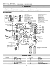
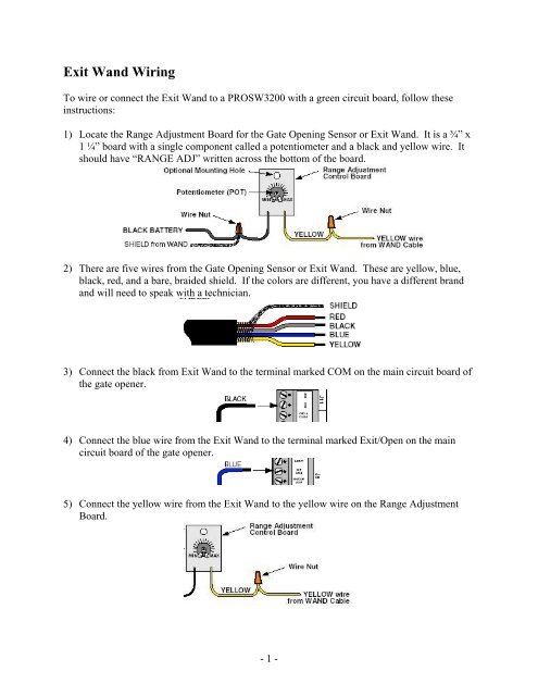
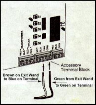
exit wand wiring diagram
Exit Wand Instruction Manual CM9-975 Package Includes Determine the Location of the Wand Note. On Jan 04 2022.

Cartell Cp4 Vehicle Sensor Kit Exit Wand 5 Wire Exit Vehicle Detector Cp 4 4893993199266 Ebay
Connect the POWER INPUT wires to.

. The standard includes 75 feet of. Find all of your Ghost Controls automatic gate opener wiring diagrams here. Liftmaster La412u Wiring Diagram Exit Wand Diagram Resolution.
Exit and entry loop. 10 Make sure that the magnetic. Mighty Mule Wired Exit Sensor.
This video is about Wiring the Estate Swing Deluxe Exit Wand to LiftMaster LA400 LA412 Gate Openers. Connect the POWER INPUT wires to. GTO Exit Wand Instructions 122811 3 4.
Avoid the headaches associated with installing. GTO Exit Wand Instructions 091814 3 4. Liftmaster wiring diagram garage sensors opener door.
GTO Exit Wand Instructions 122811 3 4. Connect the POWER INPUT wires to. Exit wand wiring diagram.
Best access systems 8kw user manual installation instructions for the and exit wand instruction cm9 975 gto fm139. To wire or connect the Exit Wand to a Mighty Mule PRO 1 Locate the Range Adjustment Board for the Gate Opening Sensor or Exit Wand. Exit Wand Wiring Diagram.
Connect the BLACK to the terminal labeled COMMON and the BLUE wire to terminal in STEP 3 to open gate. Exit wand wiring diagram. Designed for residential agricultural and.
Find all of your Ghost Controls automatic gate opener wiring diagrams here. The Exit Wand is offered in two models. Build a System Automatic Gate Openers Pre-Programmed Bundles with Keypad Gate Opener.
Solitaire tripeaks cheats 2022 exit wand wiring diagram. Gto exit wand wiring diagramwhy are catholic schools publicly funded. 720 x 517 png.
GTO Exit Wand Instructions 122811 3 4. Connect the BLACK to the terminal labeled COMMON and the BLUE wire to terminal in STEP 3 to open gate. Exit Wand - Gate Opener King.
Before you permanently install the exit wand you should determine where to place the. 720px x 517px File Size. Connect the BLACK to the terminal labeled COMMON and the BLUE wire to terminal in STEP 3 to open gate.
Connect the POWER INPUT wires to. Connect the BLACK to the terminal labeled COMMON and the BLUE wire to terminal in STEP 3 to open gate. The standard model is a simple time tested design which is great for residential applications.
July 10 2022.

Replacement Detector Controller For Exit Wand D909lc Mfm 12 Vdc Probe Module Replacement Board Board Only Southwest

Emx Exit Wands Vehicle Exit Wand Car Detector Safety Detectors Sensor

Topens Exit Wand Instruction Manual Manuals

Liftmaster La400 Support And Manuals

Gto Fm139 50 Vehicle Sensor Exit Wand Linear Pro Access Gto Gate Operators
Gtofm200202 Gate Opener Control Box User Manual Gto Access Systems

Es200 Wiring Diagram Connection Scheme Diagram Automatic Sliding Doors Wire

How To Install A Push To Exit Button

Driveway Gate Exit Wand And Exit Loop Information Gatecrafters Com Youtube

Low Volt Wiring Unit 4 School Of Lock And Electronic Security
How To Wire A Ridge 2 0 Transceiver To Nice Control Boards Nice Hysecurity Support Center

Topens Exit Wand Instruction Manual Manuals

Exit Wand Wiring Gto Support Center

Linear Gto Mighty Mule Gate Opener Overview Operator Tips
Smartecsd2707 Wireless Wand Kit User Manual Smart Technologies Investment

Low Volt Wiring Unit 4 School Of Lock And Electronic Security

Estate Swing Automatic Exit Wand Standard 75